
Electromagnetic flowmeter
Overview
Electromagnetic flow meters (EMF) is a new type of flow measurement instrument developed rapidly with the development of electronic technology from 1950s to 1960s. Electromagnetic flowmeter is an instrument that uses the principle of electromagnetic induction to measure the flow of conductive fluid according to the electromotive force induced when the conductive fluid passes through the external magnetic field.
structure
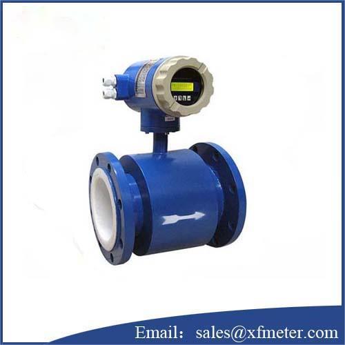
The structure of electromagnetic flowmeter is mainly composed of magnetic circuit system, measuring conduit, electrode, shell, lining and converter.
Magnetic circuit system: its function is to produce uniform DC or AC magnetic field. The DC magnetic circuit is realized by permanent magnet, which has the advantages of simple structure and less interference by AC magnetic field, but it is easy to polarize the electrolyte liquid in the measuring catheter, so that the positive electrode is surrounded by negative ions, and the negative electrode is surrounded by positive ions, that is, the polarization phenomenon of the electrode, which leads to the increase of internal resistance between the two electrodes, which seriously affects the normal operation of the instrument. When the pipe diameter is large, the permanent magnet is also large, bulky and uneconomical, so the electromagnetic flowmeter generally adopts alternating magnetic field and is excited by 50Hz power frequency power supply.
Measuring catheter: its function is to let the measured conductive liquid pass through. In order to make the magnetic flux shunted or short circuited when the magnetic force line passes through the measuring conduit, the measuring conduit must be made of materials with non-magnetic conductivity, low conductivity, low thermal conductivity and certain mechanical strength. Non-magnetic stainless steel, FRP, high-strength plastic, aluminum, etc. can be selected.
Electrode: its function is to lead out the induced potential signal proportional to the measured. Electrodes are generally made of non-magnetic stainless steel and are required to be flush with the lining so that the passage of fluid is not obstructed. Its installation position should be in the vertical direction of the pipeline to prevent sediment from accumulating on it and affecting the measurement accuracy.
Shell: made of ferromagnetic material, it is the outer cover of the distribution system excitation coil and isolates the interference of external magnetic field.
Lining: there is a complete layer of electrical insulation lining on the inner side of the measuring conduit and the flange sealing surface. It is in direct contact with the measured liquid. Its function is to increase the corrosion resistance of the measuring conduit and prevent the induced potential from being short circuited by the pipe wall of the metal measuring conduit. The lining materials are mostly corrosion-resistant, high temperature resistant and wear-resistant Teflon plastics, ceramics, etc.
Converter: the induced potential signal generated by liquid flow is very weak and greatly affected by various interference factors. The function of the converter is to amplify and convert the induced potential signal into a unified standard signal and suppress the main interference signal. Its task is to amplify and convert the induced potential signal ex detected by the electrode into a unified standard DC signal.
characteristic of Electromagnetic flowmeter
1. The measurement is not affected by the changes of fluid density, viscosity, temperature, pressure and conductivity;
2. There are no flow blocking parts and pressure loss in the measuring pipe, and the requirements for straight pipe section are low. Unique adaptability to slurry measurement;
3. Reasonably select the sensor lining and electrode material, that is, it has good corrosion resistance and wear resistance;
4. The converter adopts novel excitation mode, with low power consumption, stable zero point and high accuracy. The flow range can reach 150:1;
5. The converter can be integrated or separated with the sensor;
6. The converter adopts 16 bit high-performance microprocessor, 2x16lcd display, convenient parameter setting and reliable programming;
7. The flowmeter is a two-way measurement system with three integrators installed inside: forward total amount, reverse total amount and difference total amount; It can display positive and negative flow, and has a variety of outputs: current, pulse, digital communication, Hart;
8. The converter adopts surface mount technology (SMT) with self inspection and self diagnosis functions;
9. The measurement accuracy is not affected by the changes of fluid density, viscosity, temperature, pressure and conductivity. The sensor induced voltage signal has a linear relationship with the average flow rate, so the measurement accuracy is high.
10. There is no pressure loss in the pipeline, so there is no additional flow resistance; There are no movable parts in the measuring pipe, so the service life of the sensor is very long.
11. Because the induced voltage signal is formed in the whole space full of magnetic field and is the average value on the pipe load surface, the straight pipe section required by the sensor is short and the length is 5 times the pipe diameter.
12. The converter adopts the latest and most advanced single chip microcomputer (MCU) and surface mount technology (SMT), with reliable performance, high precision, low power consumption, stable zero point and convenient parameter setting. Click the Chinese LCD to display the cumulative flow, instantaneous flow, flow rate, flow percentage, etc.
13. Two way measurement system can measure forward flow and reverse flow. Special production technology and high-quality materials are adopted to ensure that the performance of the product remains stable for a long time.
classification
According to different types of applied magnetic field, electromagnetic flowmeter mainly includes DC type and induction type. The applied constant lower magnetic field B of the DC electromagnetic current drought meter (Fig. 2) is perpendicular to the tube axis, and two electrodes are installed at C and D to measure the electromotive force u induced by the fluid crossing the magnetic field. The flow Q can be calculated by the following formula:
Where a is the cross-sectional area of the pipeline; D is the pipe diameter; K is the correction coefficient, which is used to correct the influence of factors not taken into account when deriving the formula (such as the fact that the flow velocity in the flowmeter pipe is not uniform). In the normal flowmeter, K is about 0.8, but for the electromagnetic flowmeter with specific size and working conditions, the volume method (the volume flowing in a certain time) should be used to calibrate K. The magnetic field can be generated by permanent magnets, which are generally made of aluminum nickel cobalt alloy. When the flow is large, due to the large pipe diameter, the coreless excitation winding is used to generate an approximately uniform magnetic field through its constant DC current.
Inductive electromagnetic flowmeter can be used when the temperature of the measured fluid is too high or has strong corrosion effect on the electrode (Fig. 2). A. B refers to two AC excitation windings with equal turns (the cross section is shown in the figure). The windings are connected in series, but their current directions are opposite. When the fluid is stationary, the synthetic magnetic flux through the induction coil C is zero, so there is no induced alternating electromotive force in the coil. When the fluid flows, an alternating electromotive force is generated in the induction coil, which is directly proportional to the flow rate. Based on this principle, there are many modification schemes. For example, an excitation winding is used, and an induction coil in the opposite direction is arranged on both sides of its symmetry and connected in series (Fig. 3). When the fluid flows, the magnetic line of force moves in the flow direction, so that the electromotive force in the induction coils on both sides is not zero, which can indirectly show the size of the flow.
There are no other components in the pipeline of the electromagnetic flowmeter, so it can be used to measure the flow of non-conductive liquids with various viscosities (in which easily ionized substances are added) in addition to measuring the flow of conductive fluids. Electromagnetic flowmeter is often used in nuclear energy industry.
|
Model |
LDG LDE LDCK |
|
Size |
DN10〜DN1800 |
|
Material |
PTFE, Soft rubber, Hard rubber, F46, FS, PUR. |
|
Electrode |
316L, Hastelloy C, Hastelloy B, Titanium, Tantalum, etc. |
|
Accuracy |
0.3% (Option), 0.5%, 1.0% of F.S.. |
|
Output |
4-20ma |
|
Communication |
RS-232; RS-485; HART |
Contact: Kevin
Phone: +8615189522935
Tel: +86-517-86800063
Whatsapp: +8615189522935
Email: sales@xfmeter.com
Add: No.118 HengyangNanRoad, Jinhu County, Huaian,Jiangsu, China
We chat